Complete Guide on How to Understand the Dimensioning Rules in Mechanical Bearing Drawing
- Share
- Issue Time
- Aug 26,2019
Summary
The bearing drawing has wide applications in the history of graphics. Therefore, bearing drawings are an essential step in the production of bearings.
Complete Guide on How to Understand the Dimensioning Rules in Mechanical Bearing Drawing
Since labor initiated the history of human civilization, graphics, like languages and words, have been basic tools for people to understand nature, express and exchange ideas. Bearing drawing has wide applications in the history of graphic development through continuous improvement and development. Therefore, bearing drawings are an essential step in the production of bearings
Basic rules of mechanical bearing drawing
Bearing sizes marked on the drawing decide the bearing actual size. The bearing actual size has nothing to do with the size of the graphic and the accuracy of the bearing drawing.
Bearing drawing dimensions (including technical requirements and other instructions), in mm, does not need to indicate the code or name of the unit of measurement. If other units are used, the code or name of the corresponding unit of measurement must be indicated.
The size marked in the drawing is the final finished dimension of the bearing parts shown in this drawing. If it is not this dimension, you must add a note.
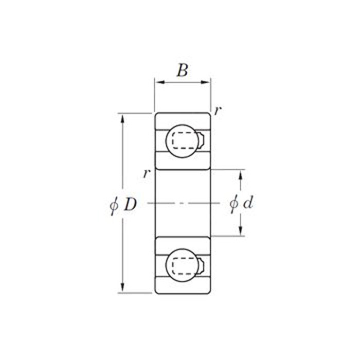
In general, mark the bearing dimensions on the drawing only once. And you should mark on the graphic that reflects the structure most clearly.
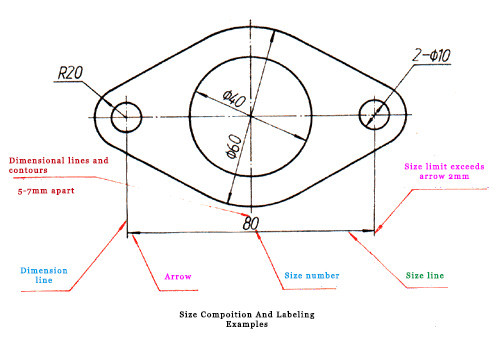
Size composition of bearing drawing
As shown in the figure below, a complete size should generally include size numbers, dimension lines, extension lines, and arrows or diagonal lines that indicate the end of the dimension line.
1. Size figures
Normally, designers mark the dimensions of linear dimensions above the dimension line. Also, it allows marking on the break of the dimension line.
2. Size line
Drawing the bearing dimension line with a thin solid line only. Generally, they must not coincide with other lines or draw on their extension lines. While dimensioning a linear dimension, the dimension line must be parallel to the dimensioned line segment. If there are several parallel dimension lines, the large dimension should be outside the small dimension to avoid the dimension line intersecting the dimension line.
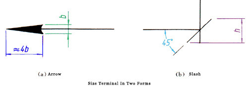
When dimensioning a circle or radius on a circle or arc, the dimension line should generally pass through the center of the circle or extension. The terminal of the dimension line has two forms, as shown in the figure: the arrow is applicable to various types of patterns, b in the figure is the width of the thick solid line. The oblique line is drawn with a thin solid line, and h in the figure is the font height. Make the end of the circle diameter, arc radius, and angle dimension line like an arrow. When using the slash form, the dimension line and the extension line must be perpendicular to each other.
3. Dimension line
If you want to draw the extension line, use the thin solid line. In addition, draw the extension line through the outline, axis, and centerline of a figure. It is also possible to use a contour line, an axis, or an asymmetrical center line as the extension line. Generally, the extension line is perpendicular to the dimension line and beyond about 2 mm with the end of the dimension line.